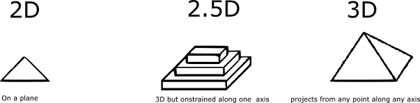
Basic Idea of CNC Milling.
Objectives
Individual Assignment
1)Make (design+mill+assemble) something big (~meter-scale).
Group Assignment
1)Test run-out, alignment, speeds, feeds, and tool paths for your machine.
>I tried to understand various CNC machining operations further from here.
>I learned what G-Code is and it’s fundamentals from here.
>Jogin asked all of us to do this bookshelf tutorial from end to end before we start designing and it helped immensely.
>I also looked up some old Assignments and Pintrest and I need to do something new other than chairs and table.
Basic Idea of CNC Milling.
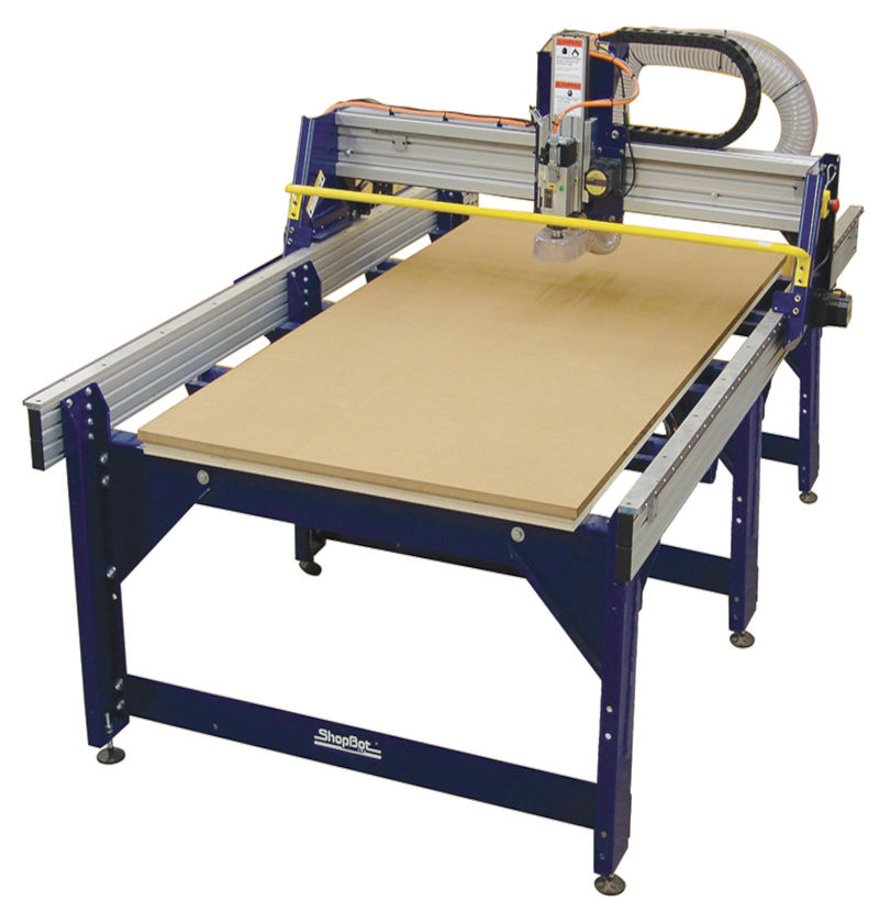
Shopbot
Material Capability- Almost all materials from Plastic and Plywood, MDF, Soft & Hardwood etc except metal or anything that requires cutting lubrication
Data Format- gcode
Gcode (tool path) Generation Software- 3D-CAM, VCarve, Fusion360 (we used Vcarve)
Data Format(2D)- svg, dxf, dwg, eps, ai, pdf, skp
Data Format(3D)- stl, obj
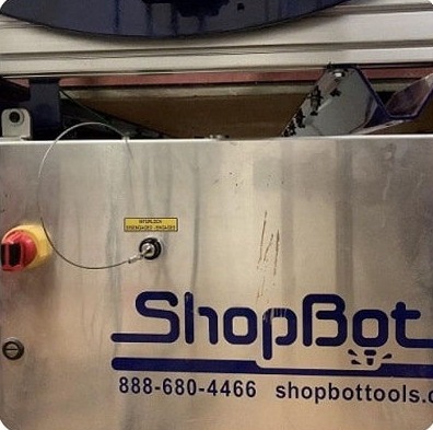
Control Box.
Control Box:
All the electronics are integrated into the shopbot main control box.It has a Machine ON/OFF switch and a Spindle Lock/Unlock key switch (disallows/allows milling head spindle rotation). After the Spindle key is inserted turning it clockwise once Switches it ON. The shopbot also has an additional Emergency Stop Switch placed on the other side, so that the user could access the emergency button easily from that side of the machine.
The bed is the cutting platform and its size is 1300mm along x-axis 1200mm along Y-axis and 150mm along z-axis. The X and Y axis are the length and the breadth of the bed respectively. The Z axis is perpendicular to the bed and its length depends on the length of the end mill. To have a rigid supporting layer on the bottom of the work piece an additional piece of plywood is placed above the bed called the sacrificial layer.The sacrificial layer also protects the milling bit from the damage that may occur by avoiding unwanted touching with the metal body.
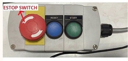
Hand Controller
Shopbot has a wired remote hand controller which consists of an emergency Stop (ESTOP) Switch, a reset switch and a spindle start button(Important). In case of emergency the machine can be stopped using the ESTOP switch.
Stopping using emergency stop button wont resume the operation, hence it is advisable that it is used only in case of real emergency. At all other times, keep a finger ready on the Space bar key of the computer to pause the operation.you can also adjust the spindle speed by shift + </>,And you have to run spindle for almost 2 minutes for a cold start.t
Drill bit Vs End mills
A drill bit need to cut straight into the material hence will have teeth at tip. But an End mill needs to cut from the sides also, that means it needs to have a cutting edge spiraling all the way up to the flute.(Rahul S Rajan)
Flutes :-
Flutes are the spiraling shafts cut along the surface of an end mill. They serve two purposes, one for cutting the material and other for clearing the wood chips from the cutting area. Less number of flutes means chips will be cleared easily but the cut will be of rough finish. Higher the number of flutes the smoother the surface, but the chips will not be cleared easily.
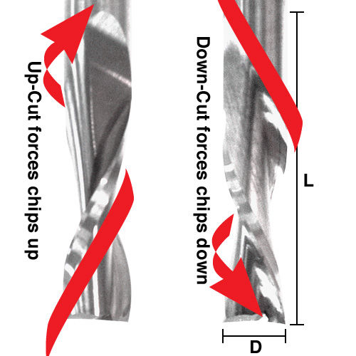
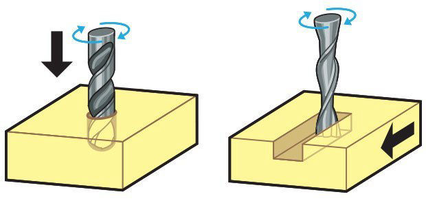
Upcut VS Downcut
In an Upcut type end mill the teeth on the flute will point upwards. This means that the end mill is cutting and drawing out the wood through the flute. This is good for cutting deep into the stock. But this leaves a bad surface finish on the top of the surface.
A downcut type end mill has teeth that point downward on the flute. This means that the end mill will cut and try to push the material into the stock. This will give good surface finish on the top, but it is not very efficient at removing material.
You can slide over the bit using fingers and differentiate between up cut mill and down cut mills.
Step-over
Chip load :- This is the amount of material that is removed in each chip. The value is approximately = feed rate (inches per minute) / (RPM x number of flutes)
Cut depth :- This is the measure of how deep the end mill should go in each step while milling. Ideally cut depths should be less than 1/3rd of the length of the tool. They are mentioned in the product manual of the tool bits.
Step-Over:-the cut is series of paths that cover the entire length and width of the cut. While doing this the step over determines how much the adjacent paths overlap each other. Usually we use it at 50%, ie the adjacent end mill cuts will overlap 50%, which gives a better finish.
Feed Rate:- The speed at which a bit can move sideways through the material. It is measured in Inch Per Minute or Feet Per Minute. If the chips are unnecessarily large, reduce the feed rate or this will ruin the bit.
Happy Milling.
>Never work with ShopBot when you are distracted
>Its important to wear eye protection,shoe and gloves at all times. The machine spindle is rotating at 12000RPM, it can and will spit out high speed projectiles at you
>Always check the spindle speed and feed rate because it can generate heat and the wood chips will get fire and thats a dead story soo beee carefull.
So,I decided to make working cycle using gear train.firstly i started design ply model in SolidWorks.My bach mate Palab also helped me too much coming up with the ply design.
I took standard bike rations to come up with bike frame.
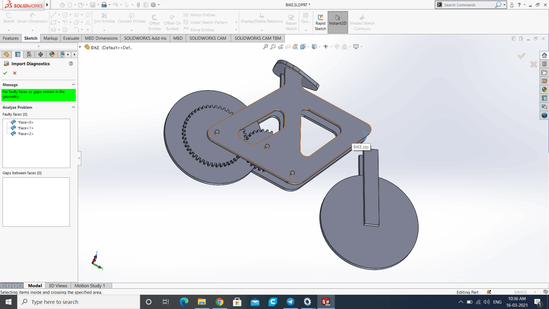
Initial Design.
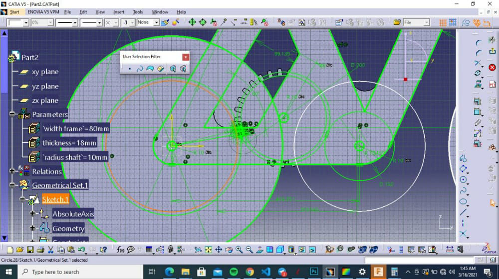
For designing gears first i just tried to array the single gear mesh throuh a circular path.then I remember the gear train involve lot of mechanical calculation.so for a gear train the gears should have same module=(number of teeth/pitch diameter).
Failed Atempt to make gears.
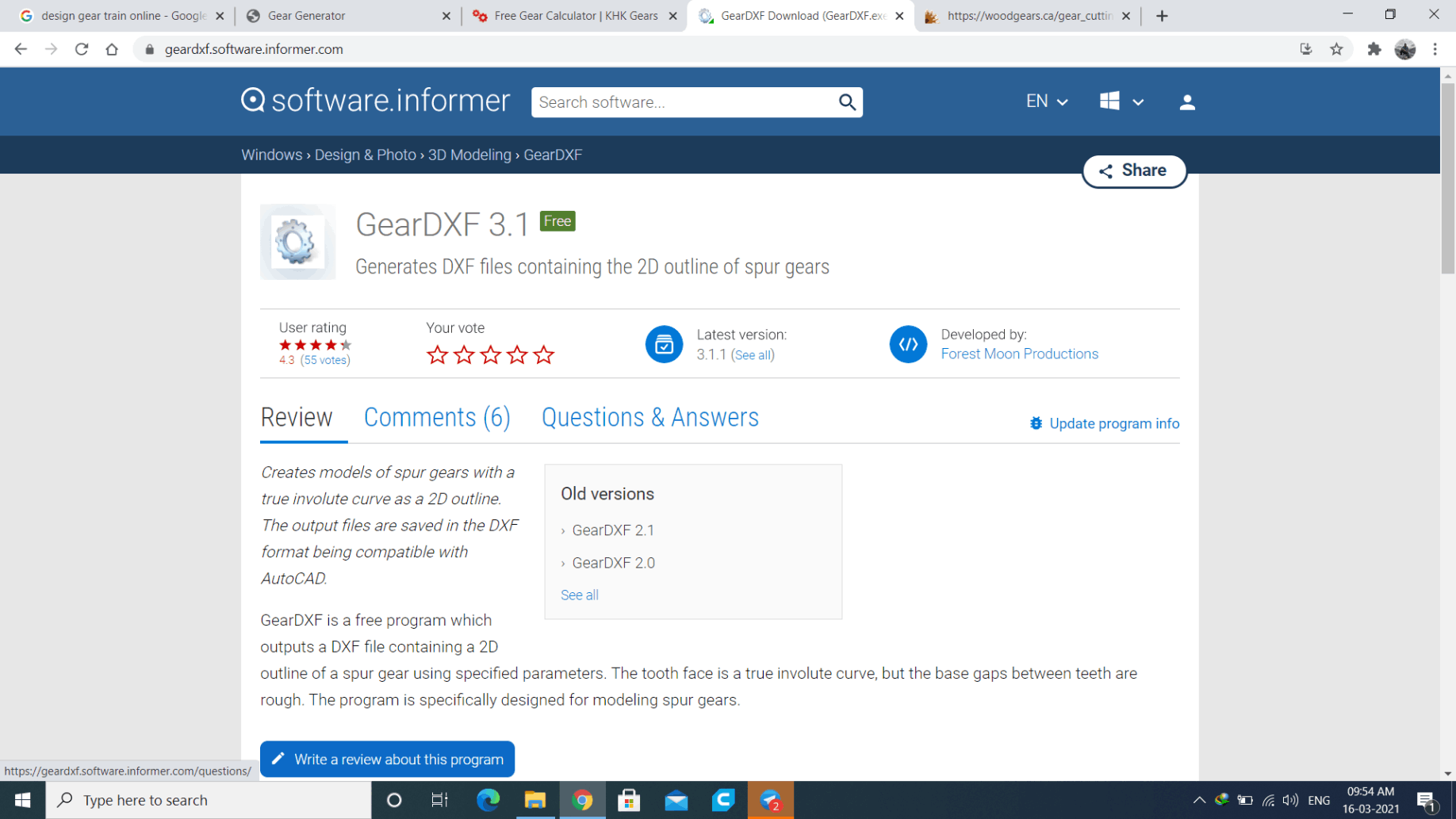
i tried many only generates but GearDXf was the best and it out a .dxf 2D file.
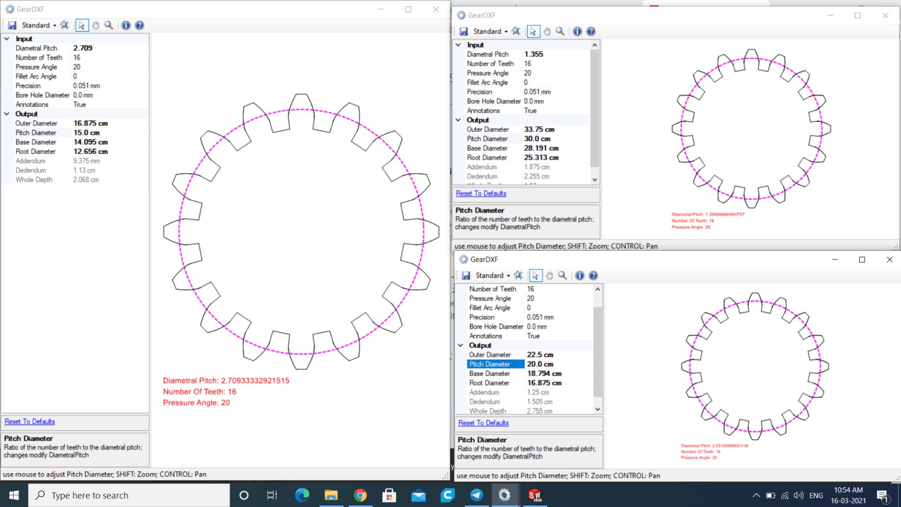
By fixing module I created and export .dxf file for the 3 gears
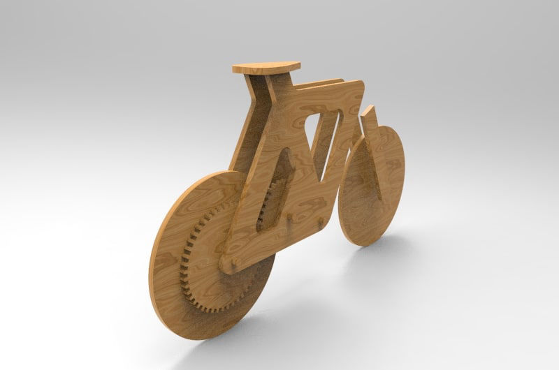
Rendered Image.
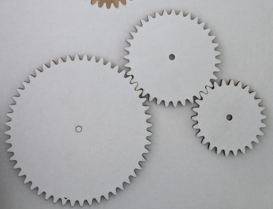
laser cut it and verified if the design is good. the thing you have to remember while designing id the fillet arc angle is very much dependent on tool size that used.
Site was designed with Mobirise